| |
DataSat
CDMA Development System provides fast, cost effective prototyping alternative
to current VSAT systems
 Download
the datasheet!
Download
the datasheet!
Rotselaar,
Belgium, April 1999
Sirius Communications
NV, a world leader in spread spectrum/CDMA technology, has just announced
the introduction of the DataSat CDMA Development System, a single-chassis
system that delivers a quantum leap forward in fast, low-cost CDMA technology
for wireless, mobile, and satellite communications.
The DataSat
System offers users a highly suitable alternative to current VSAT systems.
It works with all current satellite bands, including the KUband for Internet
data communications. And, current TV satellite receiver antennas
may be used to receive the signals.
The DataSat
CDMA Development System provides n*64 Kbits/s of bi-directional data traffic.
Its spread spectrum/CDMA modulation provides efficient interference rejection,
low power spectral density, and improved signal security over other systems.
It is directly compatible with Sirius' ASTRA Development Board and CDMA
Development Accelerator for satellite terminal prototyping.
User data rates
for DataSat are programmable over a continuous range from 1.2 kbits
up to 64 Kbits/s per channel. Up to 6 simultaneous CDMA/PSK
channels can be transmitted or received by a single DataSat CDMA Development
System. Depending upon the data rate, a processing gain of 15 to
30 dB is attainable.This provides an efficient cancellation of in-band
interference (both narrowband and broadband), and allows the system to
operate on transponder channels that suffer from high adjacent channel
interference without having to increase the transmit power.
The spreading
over 3.5 MHz-wide channels allows for a considerable reduction of the power
spectral density, thereby reducing the equipment cost as compared to traditional
PSK-based VSAT systems. The use of custom spreading codes ensures
secure communications. Both the length and content of the spreading
codes are downloadable. A variety of modulation schemes can be selected,
including BPSK, (O)QPSK, (O)QPN, and differential PSK schemes. The
cascaded Reed-Solomon (204, 188) and standard CCSDS convolutional scheme
provide an outstanding Eb/No versus BER performance for critical
applications.
The carrier
frequency acquisition range and the integration time for PN chip phase
acquisition of the DataSat CDMA Development System are user-programmable.
This makes the probability of wrong acquisition arbitrarily small, even
in very harsh channel circumstances.
The Intermediate
Frequency (IF) interface is set at 70MHz. High-rejection SAW filters
provide excellent band definition. The analog receiver front end
includes an AGC with over 40 dB of dynamic range. Data I/O is supported
through RS-232 and RS-422 interfaces. For link analysis purposes,
a PC command interface and a graphical user interface support tuning of
the customer-defined ground station parameters during development.
I, Q constellation plots, correlation values and tracking loop control
variables can be graphically monitored in real-time.
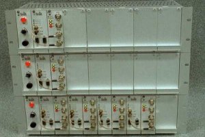
The new DataSat
CDMA Development System is mounted in a 19" rack with its own power supply
module. And, since the physical layer hardware is built around Sirius
Communications' SC2001 ASTRA CDMA transceiver IC, a significant size reduction
is possible when turning the Development System into a multi-channel CDMA
satellite modem after its duties in modeling and tuning are completed.
Integrated
CDMA Spread Spectrum Chips Challenging GPS
An encapsulated
technology offers an alternative to GPS-Based geolocation solutions.
The recent
rapid evolution of the Satcom terminal market has opened up a number of
areas that are ripe for new product development. One of these areas is
geolocation. Devices used in geolocation applications, with 2-way messaging
capabilities, could have an immediate impact in applications such as containerized
surface transportation in the tracking of freight from door-to-door on
a global basis. Another might be in the area of automotive safety and security,
in which stolen vehicles could be traced and tracked from the moment of
the discovery of their loss to their ultimate recovery. Another might be
in the rescue of downed pilots, or lost small watercraft. The list of potentials
is quite long.
Market pressures
demand that products be as small as possible, stay current with fast paced
technology changes -- and be highly cost effective. Finding low risk solutions
that optimize these demands is a challenge for providers of data services.
In this article, we will discuss the incorporation of spread spectrum CDMA
into the Transport Asset Communicator (TAC) developed by Eagle Eye Technologies
Inc. The combination of this technology with a Doppler/Ranging based position
fix algorithm could overcome the issues which make GPS approaches just
not quite good enough. Sirius Communications NV ASIC design approach of
developing the system board with standard ASICs before committing to custom
silicon enabled Eagle Eye to develop and produce proof-of-concept units
(3 x 5 x 1 inch) for field tests and software development. These units
allowed for those final "tweeks" that are inevitable in any custom ASIC
development , yet they operated as if they contained the final custom silicon.
Eliminating the need to do several spins of the ASIC design can provide
a major reduction in cost and time.
Geolocation
Applications: unique technological requirements
A.T. Kearney
recently reported that in the period 1991- 1996, although containerized
freight volume grew by 9.4%, revenue grew by only 4.1%. With the transportation
industry plagued by overcapacity and intense rate competition, a freight
carrier's survival depends on its ability to rationalize costs, boost asset
utilization, and achieve economies of scale. This has driven a global consolidation
of the industry through mergers.
Overland carriers
face similar globalization, rate competition and consolidation. There are
over 18 million commercial trucks and 4 million truck trailers operating
in the US alone (1995 DOT Census data). Like their oceangoing counterparts,
overland carriers will reap grand economies from integration in the global
transportation network, with streamlined operations, faster delivery, smaller
fleets, and reduced inventory loss. As a result, there is strong interest
in wireless location-based messaging; or geolocation, in both the container
and truck industry.
Rail carriers
using tracking tags to track rolling stock have shown a vast increase in
efficiency and utilization of capital assets, their freight cars. Trucks
and containers are not confined to railroad tracks and are even more prone
to crossing international borders. In order to track these items a wireless
satellite-based tracking system must be used.
In order to
develop a low risk solution to these markets needs, certain requirements
have to be met by any new geolocation device in order to make them better
than current GPS-based solutions to the same problems. The solution has
to incorporate the latest technology, be compact, highly accurate, cost
effective and have a fast time to market.
Combined
Doppler/Ranging versus GPS
The solution
to these unique geolocation application design requirements - based on
preliminary efforts - may well be in the use of highly integrated CDMA
chips that have already shown great promise. CDMA is a highly efficient
way of using the available radio spectrum. Using it enables the designer
to solve both the geolocation requirements and the two-way messaging needs
in a single waveform while eliminating the interference normally found
in other systems. In the geolocation approach, a ground terminal is interrogated
via satellite from another ground station. The terminal, in turn, generates
a signal to be uplinked. This return signal contains all the required user
data and acknowledges the initial signal. When received back at the ground
station, the return data are demodulated, and the position is calculated
based on the characteristics and information contained in the signal from
the terminal.
 |
|
The geolocation
approach utilizes a combination of time of arrival and frequency of arrival
to determine location. The accuracy of this approach rivals the results
of any GPS-based solution. |
| The Spread
Spectrum waveform far exceeds the strength of traditional GPS-based systems.
It can penetrate concrete walls and floors of buildings, thereby making
precise locating of objects such as automobiles in hi-rise urban parking
garages quite easy. In addition, GPS systems normally require more satellites
in view, which is another urban problem. |
|
 |
Typical LEO satellite
communications systems have high Doppler Shifts (up to 50 kHz), and Doppler
rates of over 250 Hz/s. And, the useful signals are buried in the multiple
access interference produced by other links on the same frequency band.
Design Considerations
The baseband
portion of a typical CDMA-based satellite terminal for low-to-medium data
rate transmission consists of both hardware and software modules. The digital
functions are processed at a multiple of the chip rate by the hardware.
Functions at symbol rate and control tasks are controlled by software.
The figure
shows the digital hardware of a highly integrated CDMA baseband IC. Sirius'
SC2001 ASTRA ASSP (Application Specific Standard Product) is a fully digital
CDMA transceiver chip with a DSP interface, and interfacing with an RF
front-end at a programmable Intermediate Frequency. It acts as a Spread
Spectrum processor for many CDMA-based satellite applications. The "transmit"
chain of the chip consists of a spread spectrum modulator, a RAM for on-chip
downloading spreading sequences, a Root Raised Cosine pulse-shaping filter,
a gain control and tunable upconverter to an IF. Two (O)QPSK transmit channels
are digitally combined, filtered and upconverted. The I- and Q-branches
are spread with orthogonal sequences. The "receiver" chain consists of
a programmable downconverter, a gain control function, a programmable decimation
filter, a Root Raised Cosine receive filter and correlators for dual channel
demodulation, tracking and total band energy estimation. An external DSP
processor performs parameter settings, receiver loop control, and the execution
of application-dependent algorithms.
The software
part of the satellite modem functionality is performed by a Digital Signal
Processor. At power up, the DSP is one of the first components activated.
It controls the parameterization of the digital and RF hardware. Once the
hardware is properly configured, the acquisition software attempts to reach
an initial synchronization with the satellite receive signal. This acquisition
software, which consists of a joint search for both the PN code phase and
the carrier frequency, is particularly complicated for low-rate LEO satellite
communication. The acquisition phase consists of both hardware control
tasks and software processing. Once this synchronization is achieved, the
terminal enters into a tracking mode, which attempts to keep the terminal
locked to the satellite receive signal by closing several feedback loops.
After error decoding and frame header detection, the receive message is
recovered, the raw geolocation parameters are extracted, and an uplink
signal is generated. The software puts the front end in transmit mode,
and the return signal is transmitted. As a final main task, the software
puts the terminal into a power-saving mode
Flexible
Development Boards - A Designer's Best Tool
Designers working
on geolocation and messaging devices will find that they will need to reach
"proof-of-concept" stage as early as possible. This is best done with a
flexible development board consisting of a flexible CDMA chip like the
SC2001 ASTRA, and a DSP processor as their main components.
Table 1. shows
the most important parameters for most low-to-medium rate SatCom applications.
By comparing the table entries with the CDMA block diagram, it can be seen
that the functions which are most application-dependent - such as synchronization
functions - must be controlled in the software. On the other hand, spreading
and despreading are high-speed tasks which can best be executed by the
hardware. Full flexibility is reached by storing the PN sequences in the
on-chip RAM, rather than using hardware PN code generators which would
exclude the use of custom codes.
The situation
is somewhat more complex regarding the Forward Error Coding/Decoding (FEC)
functions, For low rate applications, such as the geolocation pager, these
functions can be run on the DSP. For medium rate applications, the FEC
functions can be executed on a plug-in FPGA-based board. Such plug-in boards
may also be used to provide specific I/O functions and as interfaces to
the RF front-end. After proper programming, the capabilities of the packaged
development board should be demonstrated in actual field trials, where
the final geolocation and messaging performance can be accurately measured.
From Off-the-Shelf
Components...
Developing
a new geolocation product around off-the-shelf chips and components will
get the product to market quickly. The development board (See Figure 5)
will prove the basic architecture which can now be customized before producing
silicon. But, low cost, small size and low power consumption are best proven
in this manner.
The CDMA transceiver
chip and the DSP are the "core" components of the digital subsystem. The
right choice of peripheral components such as RAM, ROM, and small programmable
logic devices are key to the ultimate mass production of the terminal.
A/D and D/A converters on the development board are clocked by the ASTRA
chip, and interface to the RF board. The programmable logic includes RF
interfacing and a "watchdog" function. A specific timekeeping IC is on
the board in order to wake the terminal up regularly. An autonomy of several
months is required for battery-powered terminals like this one. In most
cases, the duty cycle (percentage of on-time) is very low. Therefore, ultra
low power consumption must be guaranteed during the terminal's "sleep"
mode. For this the designer will need specific hardware and software functions.
...To Custom
CDMA IC
Another design
aspect of this market-driven approach is the ability to begin development
of a custom chip at the same time the ASSP-based solution is being finalized
and tested. The main motivators for a custom chip are further reductions
in size and cost. A custom IC may allow the housing of the entire satellite
paging and geolocation functions within the dimensions of a standard personal
pager. Market demands focus the custom work on integration (transceiver
capability plus A/D and D/A integration, together with on-chip processor
core and the interface for data and RF). The DSP may be replaced by an
ARM7TDMI core which will give excellent MIPS/Watt performance at low cost.
State-of-the-art CAD tools enable quick changes in the product as it evolves
through development, late in the design phase, without introducing risks
that may have been the industry norm in the past. A fast chip design ensures
fast time-to-market, and therefore market success for the customer
L. Philips and K. Mulier are with
Sirius Communications NV located in Belgium. M. Schor and M. Sullivan are
with Eagle Eye Technologies, Inc. located in Herndon, Virginia.

|
|
 |
|
A
Flexible Development System for CDMA-Based Satellite Communications
| A CDMA Development
System on top of a programmable CDMA transceiver IC allows fast prototyping
for mobile satellite communications.
CDMA (Code
Division Multiple Access) has gained increasing interest for commercial
satellite applications. |
|
 |
Promising markets
are those of mobile satellite communications where S-CDMA (Synchronous
CDMA) is exploited in a number of products and ongoing developments in
order to obtain a flexible network and capacity improvements.
Other applications
include voice and multimedia communications over satellite links, and user
return channels over DBS transponders. In this last application, the low
energy density and interference rejection capabilities of CDMA are exploited
to have DBS and user return channels simultaneously in the same frequency
bands.
Major initiatives
are going on for the deployment of CDMA-based LEO constellations, such
as Globalstar, Aries (ECCO) , SkyBridge and Ellipso. While the already
formed consortia for these constellations are primarily focusing on voice
communications, other companies are working on derivative applications
such as 2-way satellite paging and geolocation, operating under the same
constellations. Furthermore there are a number of ESA-promoted initiatives
such as MSBN (Mobile Satellite Business Network), Prodat and IRIS (Intercontinental
Retrieval of Information by Satellite) allowing voice, low rate data and
messaging applications, respectively, with vehicle-mounted terminals using
CDMA-based satellite communications .
The above mentioned
applications all have in common that they have the strong potential to
evolve into consumer-type of markets around the turn of the century. Cost,
miniaturization and power consumption are user requirements and hence the
driving forces for a specific ASIC development for the digital key components.
Furthermore there are a great number of technical boundary conditions.
In a mobile satellite channel context, these are e.g. low Signal to Noise
Ratio, shadowing and Doppler Shift. On the other hand there's the demand
for flexibility, in order to serve different applications.
The above requirements
have lead to the development of the ASTRA SC2001 (Advanced Spread Spectrum
Transceiver ASIC) chip and other CDMA satcom ASSPs (Application Specific
Standard Product) within the context of ESA projects.
Besides the
inner modem functionality, digitalization and integration of band-limiting
filters and up-and down convertors are realized: For use in the Mobile
satellite communications domain, it is required that the receiver implementation
loss is very low. Also, a high degree of programmability is possible with
the ASTRA component in order to cover a wide range of applications.
Miniaturization
of a CDMA Transceiver
The Figure
shows the block diagram of the full digital CDMA Transceiver chip: All
functionality is contained in a single 100 PQFP package operating at 3.3
V. The Tx chain and Rx chain interface with the up and down link analog
hardware via IF signal. Programming is done via an external processor,
which also closes the demodulator synchronization loops and executes the
application dependent terminal functions such as voice processing or error
coding. The demodulator can read access over a 32-bit wide data-bus. The
clock generator blocks provide the sampling clocks for all on-chip functions.
Each functional block operates at its own rate (i.e. as low as possible)
to optimize power consumption.
The ASTRA operates
at 3.3V, which is of major importance for battery-powered mobile satellite
terminals. Moreover the high-speed hardware can be switched off via software
commands by the external processor. The current in the ASTRA chip draws
drops then from 2 mA/MHz in full operation mode to less than one tenth
of this value in sleep mode.
Transmitter
Chain
The transmit
chain contains a spreader, a pulse shaping filter, gain control and a tunable
upconverter to IF. Information data are organized in complex (I,Q) streams
by the input data converter. These I and Q branches are input for the spreading
function, that spreads the symbol bits with the downloaded PN (Pseudo Noise)
Sequences. Synchronous switching between two alternative PN codes is possible.
The resulting
chip streams are passed through an 8-fold oversampled Nyquist filter in
order to obtain a shaped, band-limited signal. This CMF operation results
in a Tx spectrum without sidelobes and hence reduces the overall system
cost by allowing less stringent out-band suppression requirements for the
RF-front-end. The chip matched filter is a SRRC (Square Rooted Raised Cosine)
filter, implemented as 35-th order FIR filters. The roll-off factor of
0.4 is convenient for most satellite communications.
Additional
oversampling with a factor L between 1 and 1024 is possible. The amplitude
of the filtered and oversampled chips can be adapted dynamically by the
external processor for transmit power control.
Selection of
the modulation scheme and translation of the spread signal to an IF is
done in the upconverter block. All PSK-like modulation schemes can be selected.
Parallel transmission of 2 CDMA/QPSK or 4 CDMA/BPSK channels with one single
chip is supported, which leads to a considerable cost and size reduction.
Also QPN (Quadrature Pseudo Noise) which is like the QPSK scheme but using
different spreading codes for the I and the Q branches is possible. Via
runtime control of the 32-bit increment fields of the CORDIC NCO, frequency
control, which is important for e.g. Doppler shift pre-compensation, of
all upconversion stages can be done digitally. By programming the appropriate
L-factor, low-rate chip streams can be modulated on very accurately defined
IF carriers.
Receiver
Chain
In the receiver
chain, the downconverted and PSK-demodulated complex signal components
are passed through a programmable M-fold decimation filter. This permits
adaptation of the sampling rate for compatibility with available analog
ICs performing the RF downconversion process.
The receiver
Chip Matched Filter outputs samples at 4 times the chip rate. These samples
are fed into a dual demodulator structure, demodulating a pilot (reference)
channel and a traffic (information) channel. The correlators calculate
the complex correlations of the traffic signal and the Early, Precise and
Late correlations of the reference signal (in total 12 parallel correlations
are calculated). Out of these correlation results, the external processor
can extract the information data and generate the synchronization parameters
for the on-chip functions. For operation in mobile satcom networks without
a pilot concept, the pilot channels can be used as extra parallel traffic
channels. In this mode, a total chip rate of 11.75 Mchips/s can be demodulated
by the ASTRA. The noise estimator function data are used to steer the transmitter
and receiver gain control functions.
Sampling
Clock Generators
The transmitter
and receiver sampling clocks are generated by sawtooth NCOs containing
32-bit accumulators running on the reference clock. The receiver sampling
clock generator is part of the PN chip phase synchronization loop. The
sampling clock generator increment of the transmitter chain can be dynamically
updated for network synchronization with Synchronous CDMA.
Special
Functions
A number of
special synchronization functions can be activated. E.g. synchronization
of the transmission start to the demodulator symbol clock is used for ranging.
Synchronous
CDMA (R. De Gaudenzi et al.) is supported by the dual demodulator receiver
architecture. The on-chip receiver can be configured as a dual-mode receiver
able to downconvert and demodulate Pilot and Traffic (information) channels.
The pilot signal carries the control data for S-CDMA networking. S-CDMA
operation reduces the self noise in the system, and hence allows to increase
the number of users sharing the same band.
A Phase Error
Measurement module is also on-chip which is an interesting feature for
use in ground stations; it provides a timing measurement with an accuracy
of 1/16th of a chip period.
| Integration
An even higher
degree of integration is possible by integrating the processor core on-chip.
The "DIRAC" e.g. integrates the receiver chain of the ASTRA, an ARM6 microprocessor
core, a S-RAM for the PN codes and a UART. |
|
 |
From the raw correlation
data, the on-chip ARM calculates DLL, PLL and AFC control variables during
tracking and acquisition, which are fed back to the appropriate data-path
registers. For this purpose, the ARM acts as the controller in a control
system with feedback. Besides, the ARM also performs the frame extraction,
the channel decoding and provides a user interface and the communication
via the serial port.
Development
System
A CDMA Development
System on top of this IC allows fast prototyping for mobile satellite communications.
This Development System basically comprises:
a 3.3V board on which the CDMA chip is combined with a TMS320-LC31 DSP
processor;
a PC-based extensive User Command Interface for interaction with this board;
a Graphical User Interface for real-time visualization of constellation
plots and demodulator variables;
A/D and D/A providing interface with RF front-end at low intermediate frequency;
a UART supporting serial data communication with RS-232 compatible peripherals.
The system allows
to rapidly deploy real-time satellite field tests and fine-tune system
parameters in the field prior to product development. The requirements
on SNR, bandwidth, IF rates, symbol rate, modulation scheme, PN code family,
Doppler shifts, Doppler rates, bit error rate and clock jitter can differ
from one application to another.
The architecture
of the Board allows to exploit this full flexibility in modulation schemes,
data rates, spreading code lengths, tracking loops, synchronization algorithms,
acquisition strategy etc.
The board features
a 16C750 UART. This serial interface can be used to feed data in or out
the modem, and it also provides you with a command line interface. This
interface allows you to observe the modem behavior, and to download any
modem parameter combination. You can check parameter settings, download
new settings and send test messages or files and measure bit error rates.
Via the command
line interface the DSP can be reprogrammed with a dedicated synchronization
algorithm too. The control part of the serial link can be removed once
the satcom modem is operational, as the parameters and the software of
the modem can be stored in the flash EPROM on the board and no external
programming device is required.
Evaluations
that can be performed with the board are:
real time sampling of the Tx baseband and IF outputs, both filtered and
unfiltered chip streams can be made externally available.
real time monitoring of the PN code Phase acquisition
real time measurements of the interrupt server execution times on the DSP.
Bit Error Rate measurements
One can also select
and continuously monitor in real-time up to 6 simultaneous receiver signals
(out of 32) such as correlation values, the receiver phase error, the AGControl
value, the carrier and the chip timing. A complex constellation diagram
can also be shown on the screen of your PC. The effect of the usersĺ parameter
settings can immediately be quantified using this tool. For instance, the
step response of the PLL for carrier recovery can be visualized as a function
of the PLL Gain and PLL Bandwidth. Any screen dump utility that supports
VGA Graphics can be used to make printouts of the achieved results and
measurements.
The following
2 examples show the system under test using QPSK with different codes of
length 15 on the I and the Q branches. This is also called QPN (Quadriphase
Pseudo-Noise).
At the left
of the screen, the 2 upper function plots show snapshots of the correlation
data of I and Q channels with each code, as a function of time. The third
functional plot shows the chip frequency offset at the receiver (D_RX_FCHIP)
and the frequency offset (D_RX_CARR) of the receiver carrier, as a function
of time.
At the right
of the screen, the constellation plot of the demodulated QPN signal is
shown.
 Lock-in
behavior of carrier tracking PLL
Lock-in
behavior of carrier tracking PLL
As a result
of a carrier frequency step at the transmitter side, the receiver carrier
frequency starts to produce a beatnote, that slows down in frequency until
lock is reached. During pull-in, correlation values are unusable, and become
stable again when lock is reached. The receiver chip frequency offset (D_RX_FCHIP)
remains unaffected. The transient behavior results in constellation dots
outside the main spots.
 Receiver
response to step in transmit chip frequency
Receiver
response to step in transmit chip frequency
In the second
example, as a result of a chip frequency step at the transmitter side,
the receiver chip frequency (D_RX_FCHIP) offset starts evolving towards
a new stable value. The receiver carrier tracking loop (see D_RX_CARR)
goes through a transient behavior, due to the coupling with the chip frequency
tracking loop, and then reaches again its original value. The Extension
Board of the CDMA Development system allows to connect other slave Development
Boards to one master Development Board in a synchronous CDMA mode for base
station and network software Development. It also allows to connect several
Development Boards in a rack for buffered serial communication for parallel
processing and for prototyping base stations.
Application
Example
| Parameter |
Application
example |
| |
|
| Net Data Rate |
16 kbps |
| IL SRRC filter
(1) |
0.1 dB |
| IL DDS (1) |
0.1 dB |
| BER |
10-4 |
| Number of
Channels |
2 parallel
QPSK channels |
| PN code |
512 (Walsh) |
| Processing
Gain |
27.08 dB |
| Chip Rate
/ Channel |
2.040 Mchips/s |
| Sensitivity
(2) |
- 116.3 dBm |
| Required S/N
at Rx Input |
-11.56 dB |
|
|
The
table shows a typical satellite application that can be realized using
the ASTRA Development Boards.
(1) Implementation
Losses of the Square Rooted Raised Cosine filter and Direct Digital Synthesis
respectively.
(2) For calculating
the expected Sensitivity figure, a typical value of 4.5 dB Insertion Loss
of the front-end has been assumed.
The specific
problems related to the development and implementation of CDMA based mobile
satellite communications are solved and addressed effectively by using
this CDMA Development environment. It allows system design engineers to
shorten considerably the design cycle for future and current mobile satcom
applications. The requirement of high flexibility has been combined with
the demand for miniaturization, low power consumption and low cost components. |
|
.jpg)
