 |
 |
|
|
 产
品 与 服 务 产
品 与 服 务 |
 技 术 资 料 技 术 资 料 |
 客 户 咨 询 客 户 咨 询 |
 关 于 我 们 关 于 我 们 |
|
|
气体超声波
超声波气体流量计概述
我们提供各种免维护的超声波与涡流多变量流量计和科氏力质量流量计,可以精准可靠地测量各种接管口径和流量。我们的固定安装流量计测量精准,用途广泛,是各种强大功能的完美结合,完全满足您的需求。我们的便携式流量计在测试、服务和故障排除方面表现出极高的灵活性和易用性。我们的产品系列包括固定安装流量计和便携式超声波流量计。
|
|
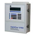
DigitalFlow GF868 - 火炬气体质量超声波流量计
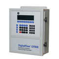
GF868火炬气流量计可以提高石化厂、炼油厂和海上平台的工作效率。它使用专有的算法即时测定火炬气分子量和质量的流量。该仪表用于节约能源,通过识别进入火炬系统的泄漏源减少产品损失。它还有助于加强符合污染控制法规,通过精确控制供给给火炬梢的蒸汽量以减少能源消耗。
即使在非定常流,脉冲压力,不同组分和温度,苛刻环境和典型火炬系统的广泛流量范围下,GF868流量计也运行可靠。流速测量从0.1到394英尺/秒(0.03到120米/秒),管道或堆栈直径达120英寸(3米)。无移动部件、孔磨损或堵塞。GF868流量测量与气体性质无关,不需要定期保养
- 速度范围:0.1 到 394
ft/sec (0.03 到 120
m/s)
-
双向流速范围:0.1到328英尺/秒(0.03到100米/秒)
- 速度、质量和体积流量
- 瞬态气体分子量
- 组分的单独测量
- 无移动部件、磨损或堵塞。
- 无需定期维护
DigitalFlow
GF868流量计是完整的超声波流量计量系统,用于测量:
- 火炬气体
- – 追踪或防止阳性材料识别的漏水
- – 占车间总吞吐量材料
- – 减少带比例控制的蒸汽使用成本
- – 消除不必要的燃烧以节约能源
- – 遵守污染控制的政府规定
- 通风气体
操作和性能
|
流体类型 |
火炬气体和通风气体 |
|
管道材料 |
全金属,玻璃纤维。其他材料请咨询GE。 |
| |
标准(100米/秒) |
|
扩展范围(120米/秒) |
|
|
管道尺寸 |
|
|
|
|
|
对角线45 |
2到14英寸(50到350毫米)NB
ANSI |
|
4到12英寸(100到300毫米)NB
ANSI |
|
|
偏差90 |
16到120英寸(400到3000毫米)NB
ANSI |
|
14到120英寸(350到3000毫米)NB
ANSI |
|
|
流量精度(流速) |
|
|
|
|
|
流量范围 |
±1到±328英尺/秒(0.3到±100米/秒) |
|
1到394英尺/秒(0.3到+120米/秒) |
|
|
单路径 |
±2-5% |
|
±2-5% |
|
|
双路径 |
±1.4-3.5% |
|
±1.4-3.5% |
|
|
流量范围 |
0.1到±1英尺/秒(0.03到±0.3米/秒) |
|
0.1到±1英尺/秒(0.03到±0.3米/秒) |
|
|
单路径 |
±0.15英寸/秒(±0.004米/秒) |
|
±0.24英寸/秒(±0.006米/秒) |
|
|
双路径 |
±0.12英寸/秒(±0.003米/秒) |
|
±0.015英寸/秒(±0.004米/秒) |
|
|
范围(整体) |
-328到328英尺/秒(-100到100米/秒)(双向) |
|
0.1到394英尺/秒(0.03到120米/秒)(非双向) |
|
|
范围度(整体) |
3280:1 |
|
3940:1 |
|
|
分子量精度(烃类混合物) |
2到120克/克摩尔 |
±1.8% |
2到6克/克摩尔 |
±2-10% |
| |
|
|
6到120克/克摩尔 |
±1.8-2% |
|
质量流量精度(备注1)(烃类混合物) |
|
|
|
|
|
单路径 |
3% 到 7% |
|
3% 到 7% |
|
|
双路径 |
2.4% 到 5% |
|
2.4% 到 5% |
|
|
备注1:取决于温度和压强输入的精度 |
|
重复性 |
±1.0%,1到394英尺/秒(30厘米/秒到120米/秒)
精度取决于管道尺寸、管道安装,以及是单路径测量还是双路径测量。±0.5%的读数精度可以凭借过程校准实现。
规格假定为全展流(典型的20直径阀前直导向管和10直径阀后直导向管),流速大于1英尺/秒(0.3米/秒)。 |
|
测量参数 |
质量流量,标准和实际体积流量,累加流量,分子量,声速和流速 |
电气设备
|
流量测量 |
受专利保护的互相关时差模式 |
|
外壳 |
标准:环氧涂层铝,防水类型4,IP66,I级,2分区,A、B、C、D组,FM和CSA
可选:不锈钢、玻璃钢、防爆、防火 |
|
尺寸 |
重量为11磅(5千克)
尺寸(高x宽x深)为14.24英寸x11.4英寸x5.12英寸(362毫米×290毫米×130毫米) |
|
通道 |
标准:单通道
可选:两个通道(两个管道或平均两个路径) |
|
显示屏 |
两个独立的可配置软件64×128像素背光LCD图形显示 |
|
键盘 |
39键触控式反馈薄膜键盘 |
|
功耗 |
最大20瓦 |
|
工作温度 |
–4°F 到 131°F
(–20°C 到
55°C) |
|
存储温度 |
–67°F 到
167°F (–55°C
到 75°C) |
|
标准输入 |
两个0/4到20毫安隔离输入(121W),集成的24VDC电源
用于所需的温度和压力输入 |
|
标准输出 |
6个4到20毫安输出,可分配软件
2个550W最大负载输出
4个1000W最大负载输出。 |
|
可选的输入/输出 |
有4个额外插槽,用于任意组合的I/O板:
带4个0/4到20毫安隔离输出的模拟输出,1千瓦最大负荷
模拟输入板:2种类型
–
有2个隔离的4到20毫安输入和24V回路电源
–
有2个隔离的三线100瓦热电阻输入:范围为
–148°F 到
662°F
(–100°C 到
350°C);
累加器/频率输出板
–
每板4个输出,最大10千赫。
–
软件可选择在两种模式下运行
–
累加模式:每定义参数组的脉冲(如1脉冲/立方英尺或1脉冲/0.028立方米)
–
频率模式:频率与参数率成正比(如10赫兹=1立方英尺/小时或0.028立方米/小时)
带有3个气密封口的C型继电器的报警继电器板,120VAC,28VDC最大,2安培最大;
DC 56瓦最大,AC
60 VA |
|
数字接口 |
标准:RS232
可选:RS485(多级接口)
可选:HART®协议
可选:Modbus®
RS485 或
TCP/IP
可选:以太网TCP/IP
可选:OPC服务器
可选:现场总线技术 |
|
显示器功能 |
图形显示器以数字或图形格式显示流量
显示记录的数据和诊断 |
|
符合欧洲标准 |
对于DN<25,
符合电磁兼容性指令2004/108/EC,
2006/95/EC
LVD(II类安装,2度污染)及PED
97/23/EC |
|
说明 |
English |
Italiano |
Português |
|
DigitalFlow™
GF868 Medidor
ultrassônico de
vazão mássico
para gás de
flare da
Panametrics |
|
|

|
|
Flare and
Vent Gas
Flowmeter
Service |

|
|
|
|
Flare Gas
Measurement Flow
Meters Brochure
(Middle East
Version) |

|
|
|
|
Flare Gas
Measurement Flow
Meters
Brochure(EU
Version) |

|

|
|
|
Flare Gas
Service Brochure
|

|
|
|
|
Get Smart on
Greenhouse Flare
Gas Flow
Measurement and
Service |

|
|
|
|
GF868 1-CH
Operating Manual |

|
|
|
|
GF868
100-120 VAC
Wiring Diagram,
Single-Channel
Unit |

|
|
|
|
GF868
100-120 VAC
Wiring Diagram,
Two-Channel Unit |

|
|
|
|
GF868
100-120 VAC
Wiring Diagram,
Two-Path Unit |

|
|
|
|
GF868 12-28
VDC Wiring
Diagram,
Single-Channel
Unit |

|
|
|
|
GF868 12-28
VDC Wiring
Diagram,
Two-Channel Unit |

|
|
|
|
GF868 12-28
VDC Wiring
Diagram,
Two-Path Unit |

|
|
|
|
GF868 2-CH
Operating Manual |

|
|
|
|
GF868
220-240 VAC
Wiring Diagram,
Single-Channel
Unit |

|
|
|
|
GF868
220-240 VAC
Wiring Diagram,
Two-Channel Unit |

|
|
|
|
GF868
220-240 VAC
Wiring Diagram,
Two-Path Unit |

|
|
|
|
GF868
Brochure(PDF) |

|

|
|
|
GF868 Gas
Flowmeter
Interconnection
Diagram,
Single-Channel
Unit |

|
|
|
|
GF868 Gas
Flowmeter
Interconnection
Diagram,
Two-Channel Unit |

|
|
|
|
GF868 Gas
Flowmeter
Interconnection
Diagram,
Two-Path Unit |

|
|
|
|
GF868 NEMA7
(Cl.1, Div.1,
Groups A-D)
Oversized
Package Outline
& Installation |

|
|
|
|
GF868 NEMA7
(Cl.1, Div.1,
Groups A-D)
Package Outline
& Installation
Drawing |

|
|
|
|
GF868
Operating Manual |

|
|
|
|
GF868 Quick
Start |

|
|
|
|
GF868
Service Manual |

|
|
|
|
GF868
Standard NEMA
4X, Wall-Mount
Package Outline
& Installation
Drawing |

|
|
|
|
HART
Communications |

|
|
|
|
MODBUS
Communications
for the GF868 |

|
|
|
|
User\'s
Guide |


|
|
|
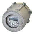
DigitalFlow XGF868i - Flare
Gas Ultrasonic Flow Meter
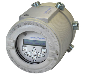
The XGF868i flare gas flow meter is a
low-cost, compact, and
explosion/flame-proof transmitter
version of the GF868 flare gas flow
meter, with CSA, ATEX, and IECEx
certifications. Like the GF868 flow
meter, the XGF868i improves the
efficiency of petrochemical plants,
refineries and offshore platforms. It
uses a proprietary algorithm to
determine instantaneously the molecular
weight and mass flow rate of the flare
gas. The meter is used to conserve
energy and reduce product loss by
identifying sources of leaks into flare
systems. It also helps improve
compliance with pollution control
regulations and reduces energy usage by
accurately controlling the amount of
steam fed to the flare tip.
The XGF868i flow meter operates reliably
even under unsteady flow, pulsating
pressure, varying composition and
temperature, harsh environments and the
wide flow ranges typical of flare
systems. Flow velocity is measurable
from 0.1 to 394 ft/s (0.03 to 120 m/s)
in pipes or stack sizes up to 120 in (3
m) in diameter. There are no moving
parts or orifices to wear or clog. The
XGF868i's flow measurement is
independent of the gas properties, and
it does not require regular maintenance.

- Measures
velocity, volumetric
and mass flow
- Delivers
accurate flow rate,
independent of gas
composition
- Measures
instantaneous
average molecular
weight
- High velocity
range to 120 m/s
(394 ft/s)
- Accurate low
flow rate
measurement
- 4000 to 1
turndown ratio
- One or two path
configurations
- Allows cross
flow immunity in
large pipes
- Minimal
maintenance due to
no moving parts, no
holes or tubes, and
tolerance to dirty
or wet conditions
- No pressure drop
- Field-proven
installation
techniques
- Easy
serviceability
The DigitalFlow XGF868i
flow meter is a complete
ultrasonic flow metering
system for:
- Flare gas:
-
Track down
or prevent
losses from
leakage with
positive
material
identification
-
Account for
total plant
throughput of
material
-
Reduce cost
of steam usage
with
proportional
control
-
Conserve
energy by
eliminating
unnecessary
flaring
-
Comply with
government
regulations for
pollution
control
- Vent gas
- Hydrocarbon
gases
- Biogases
- Digester Gases
Operation and
Performance
|
Fluid Types |
Flare and
vent gases |
|
Pipe
Materials |
All metals,
fiberglass.
Consult GE
for other
materials. |
|
Pipe Sizes |
14 in to 120
in NB ANSI
(350 to 3000
mm) |
Note 1 |
|
Flow
Accuracy
Velocity |
|
One Path |
Two Path |
Note 3 |
|
High Flow
Range |
±1.0 to ±394
ft/s
(±0.3 to
±120 m/s) |
±2.0% |
±1.5% |
Note 5 |
|
Low Flow
Range |
±0.1 to ±1.0
ft/s
(±0.03 to
±0.3 m/s) |
±0.008 ft/s
(±0.002 m/s) |
±0.0057 ft/s
(±0.0017
m/s) |
Resolution |
|
Molecular
Weight
Accuracy |
2 to 120
gr/gr mole |
±1.8% of
reading |
|
Hydrocarbon
Mixtures |
|
Mass Flow
Accuracy |
|
±2.7% |
±1.9% |
Note 2 |
|
Repeatability |
1 to 394
ft/s
(0.3 m/s to
120 m/s)
0.1 to <1.0
ft/s
(0.03 to
<0.3 m/s) |
±0.5 to 1.0%
±5 to 6% |
±0.35 to
0.75%
±3.5 to 4.0% |
|
|
Rangeability
(Overall) |
4000.1 |
|
|
|
Note 1 - For pipe
size 4 to 12 in NB,
accuracy ranges from 1.5
to 4% for 1 f/s (0.3
m/s) and greater. Please
consult GE for details.
Note 2 - Dependent
on accuracy of
temperature and pressure
inputs
Note 3 - Accuracy
stated assumes fully
developed flow profile.
Recommended minimum
straight pipe is 20
diameters upstream and
10 diameters downstream.
For 10 diameters
upstream and 5 diameters
downstream, accuracy is
5% for single path.
Note 4 - Consult GE
for accuracy of
non-standard transducer
types.
Note 5 - Accuracy to
0.5% may be achieved
with calibration.
Electronics
|
Flow
Measurement |
Patented
Correlation
Transit-Time
mode |
|
Enclosures |
Standard:
Epoxy-coated
aluminum
Optional:
Stainless
steel
Hazardous
Area Rating:
Explosionproof:
Class 1,
Division 1,
Groups B, C
& D
Flameproof:
ISSeP
07ATEX015,
II 2 G Ex d
IIC T5 IP66
IECEx: FM G
0011X
II 2 G Ex d
IIC T6 Gb
IP66 |
|
Dimensions |
Standard:
Size 8.2 in
x 6.6 in
(208 mm x
168 mm)
Weight: 10
lb (4.5 kg) |
|
Channels |
Standard:
Two channels
(for
two-path
averaging) |
|
Display |
2 line x 16
character
backlit LCD
display,
configurable
to display
up to four
measurement
parameters
in sequence |
|
Keypad |
Built-in
infrared,
six-button
keypad for
full
functionality
operation |
|
Power
Supplies |
Standard:
100 to 240
VAC
Optional: 12
to 24 VDC, ±
5% |
|
Power
Consumption |
20W maximum |
|
Operating
Temperature |
–40°F to
140°F (–40°C
to 60°C) |
|
Storage
Temperature |
–67°F to
167°F (–55°C
to 75°C) |
|
Standard
Inputs |
Two 4 to 20
mA isolated
inputs, 24
VDC loop
power, or
One 4 to 20
mA isolated
input, 24
VDC loop
power, and
One direct
three-wire
RTD
(temperature)
input,
-148°F to
662°F
(-100°C to
350°C), 100
Ω platinum |
|
Standard
Outputs |
Two 0/4 to
20 mA
isolated
outputs, 600
Ω maximum
load |
|
Optional
Inputs/Outputs |
Two
frequency
outputs,
optically
isolated, 3
A maximum,
100 VDC
maximum, 1 W
maximum,
from DC to
10 kHz
maximum |
|
Digital
Interfaces |
Standard:
RS232 (PanaView
PC software)
HART®
protocol on
4-20 mA
output
Optional:
Modbus®
RS485 or
TCP/IP
Optional:
Ethernet
Optional:
OPC Server
Optional:
Foundation
Fieldbus® |
|
Display
Functions |
Graphic
display
shows flow
in numerical
or graphic
format
Displays
logged data
and
diagnostics |
|
European
Compliance |
Complies
with EMC
Directive
2004/108/EC,
2006/95/EC
LVD
(Installation
Category II,
Pollution
Degree 2)
and
transducers
comply with
PED 97/23/EC
for DN<25 |
|
说明 |
English |
|
DigitalFlow
XGF868i
Datasheet |

|
|
DigitalFlow
XGF868i
Programming
Manual |

|
|
DigitalFlow
XGF868i Service
Manual |

|
|
DigitalFlow
XGF868i Startup
Guide |

|
|
T17
Transducer
Datasheet |

|
|
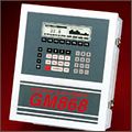
DigitalFlow GM868 - 通用气体超声波流量计
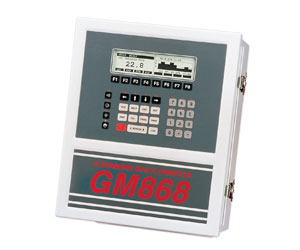
DigitalFlow™GM868通用流量计可测量管道内气体流量,管道尺寸小至0.5英寸(1.27厘米)的小导管,大至超过25英尺(7.6米)。其超声波感测器的创新配置符合管道、导管尺寸和其他应用要求。这种无阻碍仪表有很宽的可调范围,不会造成压力下降,且无需定期维护。速度和实际体积流量模拟和数字输出均为标准输出。
- 通用气体流量计
- 速度范围:0.1 到 150英尺/秒(0.03
到 46米/秒)
- 无阻碍,无压降
- 无可动部件;无需维护
- 可经受浑浊环境
DigitalFlow
GM868流量变送器是完整的超声波流量计量系统,用于测量大部分气体,如:
- 烃类气体
- 通风气体
- 沼气
- 沼气池气体
- 燃料气体
- 废气
- 焚烧炉气流
- 回收蒸气
- 烟道气
- 其他气体
操作和性能
| 流体类型 |
所有声学导电气体 |
| 管道尺寸 |
2英寸到120英寸(50毫米到3000毫米)NB,以及更大尺寸 |
| 管道材料 |
全金属。其他材料请咨询GE。 |
| 流量精度(流速) |
典型读数的±1%到2% |
|
精度取决于管道尺寸,以及是单路径测量还是双路径测量。精确至读数的±0.5%,可在校准过程中实现。 |
| 重复性 |
读数的±0.2%到0.5% |
| 范围(双向) |
-150到150英尺/秒(-46到46米/秒) |
| 范围度(整体) |
150:1 |
|
规格假定为全展流(20直径阀前直导向管和10直径阀后直导向管),流速大于3英尺/秒(1米/秒)。 |
| 测量参数 |
质量流量,标准和实际体积流量,累加流量和流速 |
电气设备
|
| 流量测量 |
受专利保护的互相关时差模式 |
| 外壳 |
-
标准:环氧涂层铝,防水类型4,IP66,I级,2分区,A、B、C、D组
- 可选:不锈钢、玻璃钢、防爆、防火
|
| 尺寸 |
标准:重量为11磅(5千克),尺寸(高x宽x深)为14.24英寸x11.4英寸x5.12英寸(362毫米×290毫米×130毫米) |
| 通道 |
- 标准:1个通道
-
可选:两个通道(两个管道或平均两个路径)
|
| 显示屏 |
两个独立的可配置软件64×128像素背光LCD图形显示 |
| 键盘 |
39键薄膜键盘 |
| 电源 |
标准:100到130
VAC,50/60赫兹或200到265VAC,50/60赫兹•可选:12
到 28 VDC, ±5% |
| 功耗 |
最大20瓦 |
| 工作温度 |
–4° 到
131°F (–20° 到 55°C) |
| 存储温度 |
–67° 到
167°F (–55° 到 75°C) |
| 标准输入/输出 |
两个0/4到20毫安隔离输出,550S最大负荷 |
| 可选的输入/输出 |
有6个额外插槽,用于任意组合的I/O板:
-
模拟输出:至多选择3个额外的输出板,各板配有4个0/4到20毫安的隔离输出,1kS最大负荷
-
模拟输入:至多选择以下类型之一的3个板:
- –
带有2个4到20毫安隔离输入的模拟输入板
- 输入和24V回路电源
- –
带有两个隔离的三线热电阻的电热阻输入板
-
输入;范围为-100°到350°C(-148°到662°F);100S
-
累加器/频率输出:至多选择3台累加器/频率输出板,每板有4个输出,最大10千赫
-
报警继电器:至多选择以下类型之一的2个板:
-
–通用:带有3个C型继电器的继电器板
- –气密封口:3个继电器板
- 气密封口的C型继电器
|
| 数字接口 |
- 标准:RS232 •
可选:RS485(多级接口)
- 可选:Modbus®
RS485或TCP协议
- 可选:以太网
- 可选:OPC服务器
- 可选:现场总线技术
|
| 数据记录 |
内存容量(线性和/或循环型),记录多达43,000个流量数据点 |
| 显示功能 |
-
图形显示器以数字或图形格式显示流量
- 显示器记录的数据和诊断
|
| 符合欧洲标准 |
对于DN<25,
符合电磁兼容性指令89/336/EEC,
73/23/EEC
LVD(II类安装,2度污染)及PED
97/23/EC |
湿式超声波流量感测器
|
| 温度范围 |
- 标准:–58° 到 302°F
(–50° 到 150°C)
- 可选(整体范围):–310° 到
842°F (–190° 到
450°C)
|
| 压强范围 |
- 标准:0 到 2,700
psig (1 到 187 bar)
- 可选:最大值为3480 psig
(240 bar)
|
| 感测器材料 |
|
| 过程连接 |
法兰和压缩配件 |
| 安装方式 |
法兰的流通池或冷水龙头 |
| 地区分类 |
- 标准:通用
可选:防风雨类型4X/IP66
-
可选:防爆、I类,2分区,ATEX
|
| 感测器电缆 |
一对RG62
AU同轴电缆,1000英尺(330米) |
| 高温和高压 |
超声波流量感测器捆绑波导技术™系统感测器和固定器(参见BWT™系统规格)压力和温度感测器依据要求提供。 |
|
说明 |
中文 |
English |
Français |
Deutsch |
Italiano |
Português |
Español |
| GM868 General
Purpose Gas Ultrasonic
Flowmeter |
|

|
|
|
|
|
|
| DigitalFlow™ GM868
Medidor de vazão de gás
ultrassônico da
Panametrics |
|
|
|
|
|

|

|
| DigitalFlow™ XGM868
Trasmettitore
ultrasonico di flusso di
gas Panametrics |
|
|
|
|

|

|
|
| GM868 100-120 VAC
Wiring Diagram,
Single-Channel Unit |
|

|
|
|
|
|
|
| GM868 100-120 VAC
Wiring Diagram,
Two-Channel Unit |
|

|
|
|
|
|
|
| GM868 100-120 VAC
Wiring Diagram, Two-Path
Unit |
|

|
|
|
|
|
|
| GM868 12-28 VDC
Wiring Diagram,
Single-Channel Unit |
|

|
|
|
|
|
|
| GM868 12-28 VDC
Wiring Diagram,
Two-Channel Unit |
|

|
|
|
|
|
|
| GM868 12-28 VDC
Wiring Diagram, Two-Path
Unit |
|

|
|
|
|
|
|
| GM868 200-240 VAC
Wiring Diagram,
Single-Channel Unit |
|

|
|
|
|
|
|
| GM868 200-240 VAC
Wiring Diagram,
Two-Channel Unit |
|

|
|
|
|
|
|
| GM868 200-240 VAC
Wiring Diagram, Two-Path
Unit |
|

|
|
|
|
|
|
| GM868 Datasheet |
|
|

|
|
|
|
|
| GM868 Flowmeter |
|

|
|
|
|
|
|
| GM868 Flowmeter 1-CH
Operating Manual |
|

|
|
|
|
|
|
| GM868 Flowmeter 2-CH
Operating Manual |
|

|
|
|
|
|
|
| GM868 Flowmeter
Operating Manual |
|

|
|
|
|
|
|
| GM868 Gas Flowmeter
Interconnection Diagram,
Single-Channel Unit |
|

|
|
|
|
|
|
| GM868 Gas Flowmeter
Interconnection Diagram,
Two-Channel Unit |
|

|
|
|
|
|
|
| GM868 Gas Flowmeter
Interconnection Diagram,
Two-Path Unit |
|

|
|
|
|
|
|
| GM868 NEMA 7 (Cl.I,
Div.1, Groups A-D)
Oversized Package
Outline & Installation
Drawing |
|

|
|
|
|
|
|
| GM868 NEMA 7 (Cl.I,
Div.1, Groups A-D)
Package Outline &
Installation Drawing |
|

|
|
|
|
|
|
| GM868 Standard NEMA
4 Package Outline &
Installation Drawing |
|

|
|
|
|
|
|
| MODBUS
Communications |
|

|
|
|
|
|
|
| User\'s Guide |
|


|

|
|
|
|
|
| XGM868i
|

|

|

|

|
|
|

|
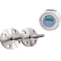
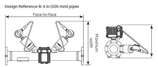
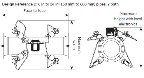
PanaFlow仪表系统 - 整体超声波流量计
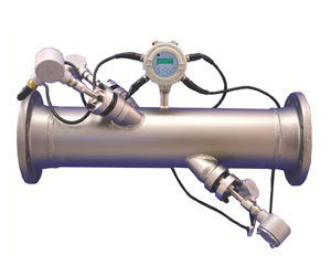
GE和PanaFlowTM仪表系统湿式超声波流量计,用于测量液体、气体或蒸汽。它使用标准的计量器,设计安装于单路径或双路径超声波感测器,以及本地或或远程电气设备。PanaFlow仪表系统设计用于天然气、燃料气、烃类液体或气体、溶剂、弱酸、水和饱和蒸汽或过热蒸汽。
PanaFlow仪表系统具有超声波流量测量的优势,包括无压降,无移动部件更换和极低维护。在完整的流量计系统中,这些优势体现在化工、石油、气体,以及其他工业中粗糙过程环境的固定安装。
|
 |
|


